Custom Sensor Magnet Manufacturer
Magnetic Targets & Sensor Magnets
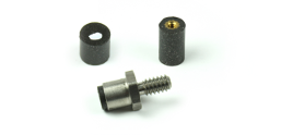
Phoenix America LLC differentiates itself from other sensor and encoder manufacturers by developing and manufacturing its own magnetic targets. At the heart of many of the Phoenix America LLC solutions are the magnetic target wheels and proximity targets. Allow the Phoenix America LLC engineering team to handle ‘both ends’ of your feedback answer by not only defining a sensor and magnetic target but by manufacturing and shipping them as an optimized total solution. Free up your engineering resources to focus on core competencies, and let Phoenix America LLC take care of your feedback requirements.
Phoenix America is a leading magnetic field sensor manufacturer. Phoenix America's multi-pole magnetized target wheels are uniquely constructed of a proprietary mix of magnet materials and engineering thermoplastics. The result is a unitized magnet target wheel that produces a very accurate, homogeneous magnetic field and has very tight mechanical tolerances. This results in a cost-effective product, compared to the traditional, high component count wheels with individual magnet bars glued into place.

Click to Contact us Today or call us at 866.315.7032