HF High Resolution Kit
Quick Overview
- Magnetic technology offers robust performance.
- 100% Non-contacting design (no bearings or bushing) provides an extremely long life expectancy and is tolerant to harsh environments.
- Simple two piece design (target magnet + encoder) for easy alignment and installation.
- Bi-directional two channel incremental quadrature output. Option for differential RS422 compatible output.
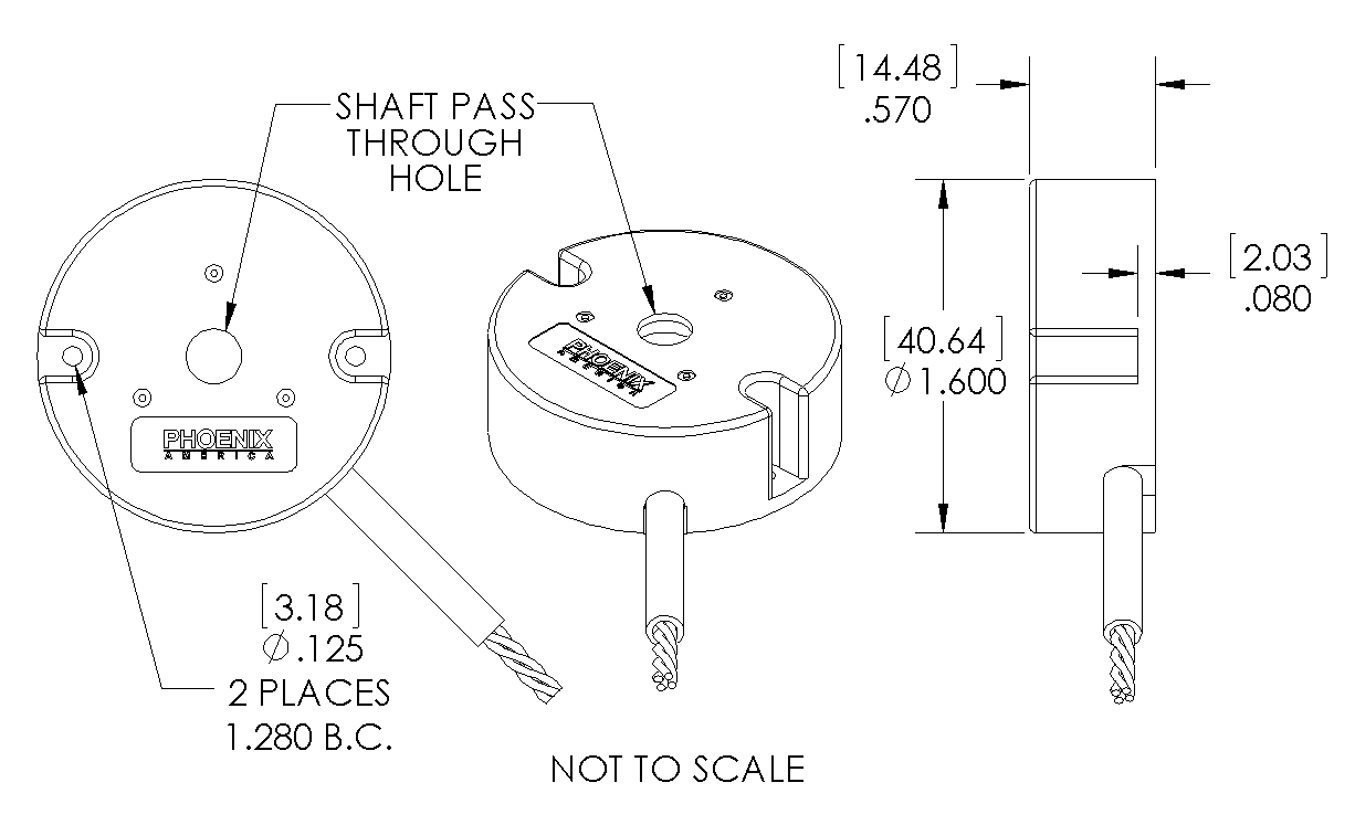
- Mounting holes for a 2-bolt pattern 1.280 inch B.C. x 0.125 inch O.D.
- Target magnet for standard shaft sizes from 2 mm to 1/2 inch. Custom bore size available.
- Options for 20 to 2560 pulse per channel per revolution (increments of 20).
- Customizable lead wires, cables, and or connectors.
- Photos
-
-
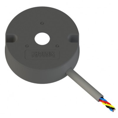 HF Encoder - Front
 -
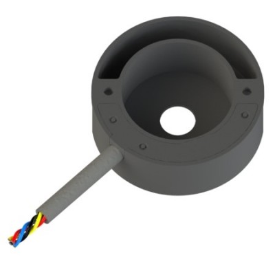 HF Encoder - Back
 -
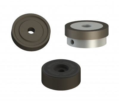 1 Inch Rotor Options
 -
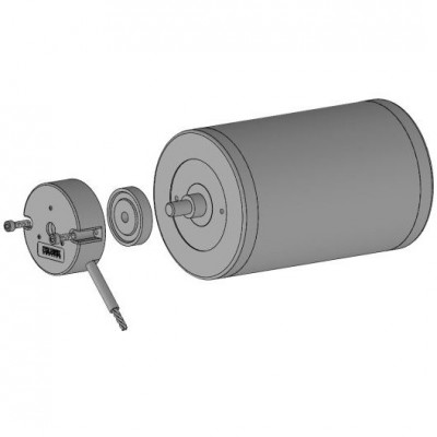 Application Example
-
- Mechanical Drawing Preview


Price:
Product Description
Part Number Configuration Guide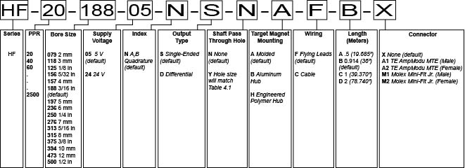
Download
Product Specifications
- Mechanical
-
Characteristic Value Standard Shaft Diameter 2 mm - 1/2 inch Mounting Screw Size M2.5 Metric / #4 English 2-Bolt Pattern 1.280 inch BC x 0.125 inch OD Motor Shaft Diameter Shaft Pass Through Hole Size 2 mm 2.06 mm 0.081 inch 3 mm 3.06 mm 0.120 inch 1/8 inch 3.26 mm 0.127 inch 5/32 inch 4.06 mm 0.160 inch 4 mm 4.06 mm 0.160 inch 3/16 inch 4.83 mm 0.190 inch 5 mm 5.06 mm 0.199 inch 6 mm 6.06 mm 0.239 inch 1/4 inch 6.40 mm 0.252 inch 7 mm 7.06 mm 0.278 inch 5/16 inch 8.05 mm 0.317 inch 8 mm 8.05 mm 0.317 inch 3/8 inch 9.59 mm 0.378 inch 10 mm 10.06 mm 0.395 inch 12 mm 12.06 mm 0.475 inch 1/2 inch 12.76 mm 0.502 inch - Electrical
-
Absolute Maximums Symbol Rating
for 5V
Rating for
6V to 24V
Units Forward Supply Voltage VCC 6
30
V Reverse Supply Voltage VRCC -0.3 -20 V
Storage Temperature TS 150 150 °C
ESD (HMB, 100pF/1.5Kohm) - 2 2 kV
5V Specifications Symbol Test Condition Min. Typ. Max. Units Supply Voltage VCC Operating,
TJ < 165 °C
4.75 5 5.5 V Supply Current ICC VCC = 12V - 14 20 mA
Operating Temperature TA - -40 - 125 °C Duty Cycle - - 40 50 60 % Phase - - 70 90 110 °e Output Frequency fOUT - - - 42 kHz
24V Specifications Symbol Test Condition Min. Typ. Max. Units Supply Voltage VCC Operating,
TJ < 165 °C
5.25 12 24 V Supply Current ICC VCC = 12V - - - mA
Operating Temperature TA - -40 - 125 °C Duty Cycle - - 40 50 60 % Phase - - 70 90 110 °e Output Frequency fOUT - - - 42 kHz
Electrical Circuit 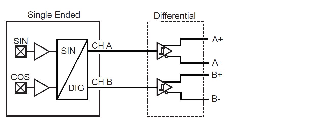
- Output Definition
-
PPR Options 20 to 2560 (Increments of 20)
Single Ended Output Waveform 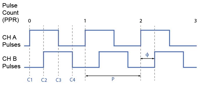
Differential Output Waveform 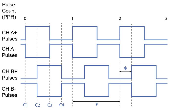
- Target Magnet
-
Molded (A) 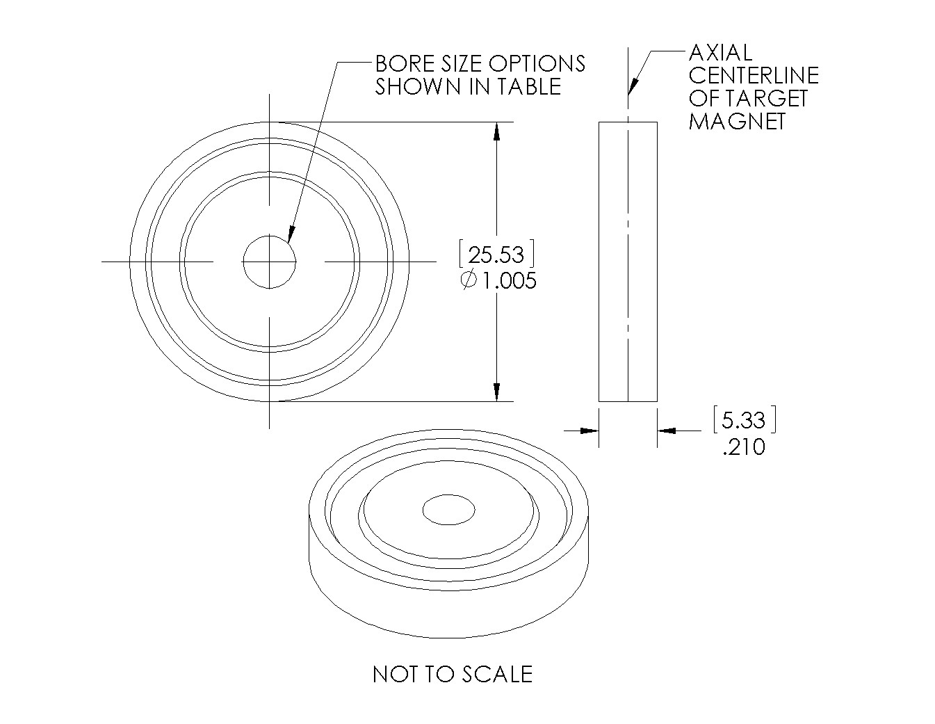
Bore Size
(.inch)
Motor Shaft
O.D. Size
NEMA Guide
Shaft Tolerance
Magnet Bore
MIN.
Magnet Bore
MAX.
079 2 mm +0.0000"/-0.0005"
.0777" .0807" 118 3 mm .1171"
.1201"
125 1/8 in .1240"
.1270"
156 5/32 in .1553"
.1583"
157 4 mm .1565"
.1595"
188 3/16 in .1865"
.1895"
197 5 mm .1959" .1989" 236 6 mm .2354" .2384" 250 1/4 in .2490" .2520" 276 7 mm .2747" .2777" 313 5/16 in .3115" .3145" 315 8 mm .3140" .3170" 375 3/8 in .3740" .3770" 394 10 mm .3930" .3960" 473 12 mm .4718" .4748" 500 1/2 in .4990" .5020" Aluminum Hub (B) 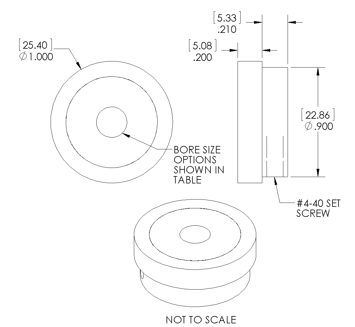
Bore Size
(.inch)
Motor Shaft
O.D. Size
NEMA Guide
Shaft Tolerance
Magnet Bore
MIN.
Magnet Bore
MAX.
079 2 mm +0.0000"/-0.0005"
.0794" .0803" 118 3 mm .1188"
.1197"
125 1/8 in .1257"
.1266"
156 5/32 in .1570"
.1579"
157 4 mm .1582"
.1591"
188 3/16 in .1882"
.1891"
197 5 mm .1976" .1985" 236 6 mm .2371" .2380" 250 1/4 in .2507" .2516" 276 7 mm .2767" .2778" 313 5/16 in .3134" .3145" 315 8 mm .3159" .3170" 375 3/8 in .3759" .3770" 394 10 mm .3949" .3960" 473 12 mm .4737" .4748" 500 1/2 in .5009" .5020" Engineered Polymer Hub (H) 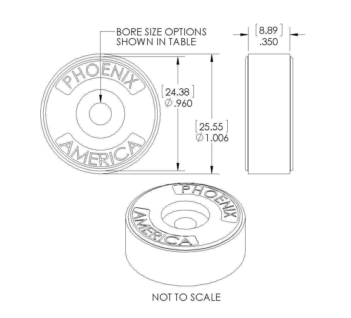
Bore Size
(.inch)
Motor Shaft
O.D. Size
NEMA Guide
Shaft Tolerance
Magnet Bore
MIN.
Magnet Bore
MAX.
079 2 mm +0.0000"/-0.0005"
.0727" .0757" 118 3 mm .1121"
.1151"
125 1/8 in .1190"
.1220"
156 5/32 in .1503"
.1533"
157 4 mm .1515"
.1545"
188 3/16 in .1815"
.1845"
197 5 mm .1909" .1939" 236 6 mm .2304" .2334" 250 1/4 in .2440" .2470" 276 7 mm .2698" .2728" 313 5/16 in .3065" .3095" 315 8 mm .3090" .3120" 375 3/8 in .3690" .3720" 394 10 mm .3880" .3910 473 12 mm .4668" .4698" 500 1/2 in .4940" .4970" - Wiring & Connection
-
Single Ended Wiring Code
Flying Leads Cable Ch A Yellow Brown Ch B Blue Orange Gnd Black Black +VCC Red Red Differential Wiring Code Flying Leads Cable Ch B Blue Orange Ch B- Orange Green Ch A Yellow Brown Ch A- Brown Yellow Gnd Black Black +VCC Red Red Wiring Options 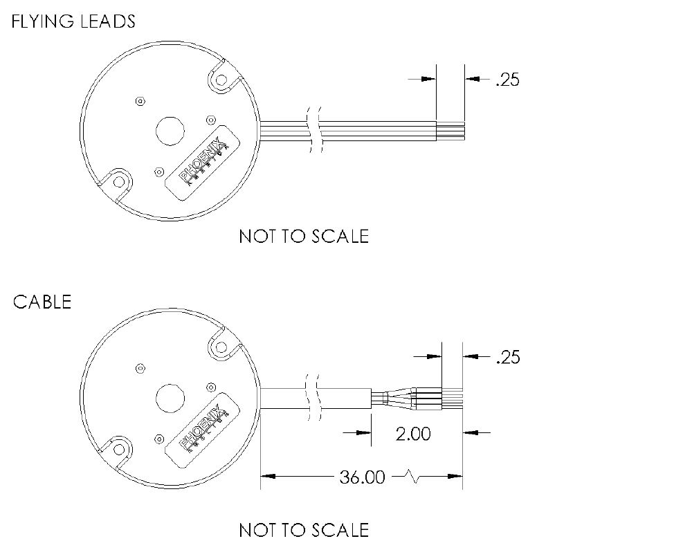
Connector Options 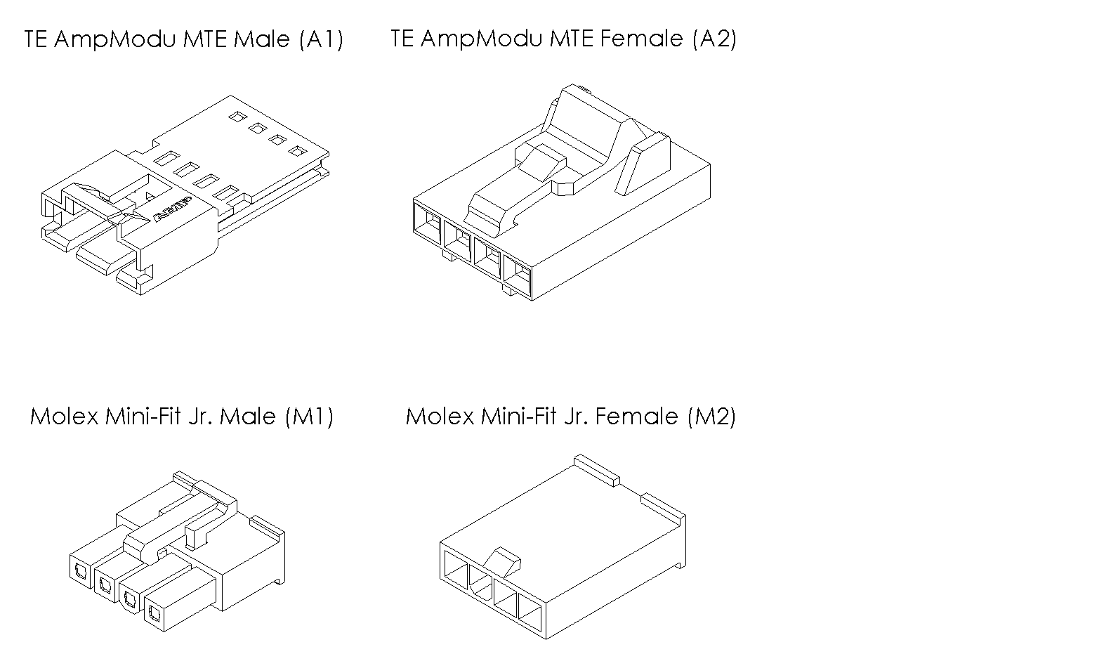
- Assembly Instruction