L6 Low Resolution Kit
Quick Overview
- Magnetic technology offers robust performance.
- 100% Non-contacting design (no bearings or bushing) provides an extremely long life expectancy and is tolerant to harsh environments.
- Simple two piece design (target magnet + encoder) for easy alignment and installation.
- Bi-directional two channel incremental quadrature output.
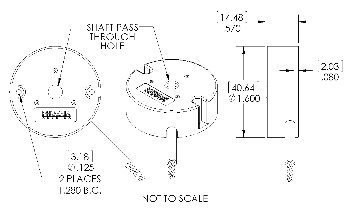
- Mounting holes for a 2-bolt pattern 1.280 inch B.C. x 0.125 inch O.D.
- Target magnet for standard shaft sizes from 2 mm to 1/2 inch. Custom bore size available.
- Options up to 30 pulse per channel per revolution.
- Customizable lead wires, cables, and or connectors.
- Photos
-
-
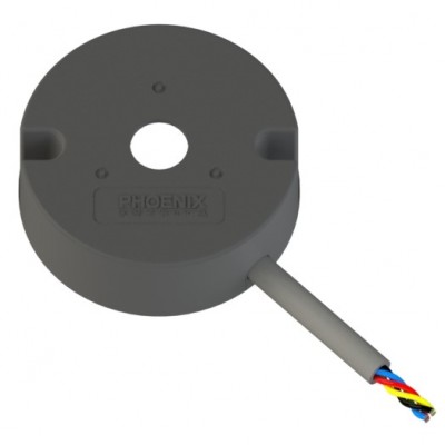 L6 Encoder - Front
 -
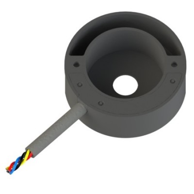 L6 Encoder - Back
 -
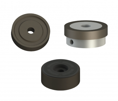 1 Inch Rotor Options
 -
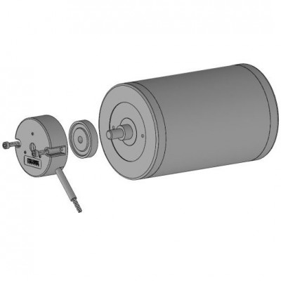 Application Example
-
- Mechanical Drawing Preview


Price:
Product Description
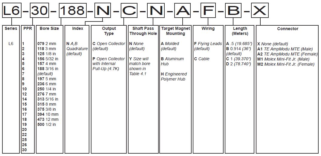
Part Number Configuration Guide
Download
Product Specifications
- Mechanical
-
Characteristic Value Standard Shaft Diameter 2 mm - 1/2 inch Mounting Screw Size M2.5 Metric / #4 English 2-Bolt Pattern 1.280 inch BC x 0.125 inch OD Motor Shaft Diameter Shaft Pass Through Hole Size 2 mm 2.06 mm 0.081 inch 3 mm 3.06 mm 0.120 inch 1/8 inch 3.26 mm 0.127 inch 5/32 inch 4.06 mm 0.160 inch 4 mm 4.06 mm 0.160 inch 3/16 inch 4.83 mm 0.190 inch 5 mm 5.06 mm 0.199 inch 6 mm 6.06 mm 0.239 inch 1/4 inch 6.40 mm 0.252 inch 7 mm 7.06 mm 0.278 inch 5/16 inch 8.05 mm 0.317 inch 8 mm 8.05 mm 0.317 inch 3/8 inch 9.59 mm 0.378 inch 10 mm 10.06 mm 0.395 inch 12 mm 12.06 mm 0.475 inch 1/2 inch 12.76 mm 0.502 inch - Electrical
-
Absolute Maximums Symbol Rating Units Forward Supply Voltage VCC 32
V
Reverse Supply Voltage VRCC
-0.3 V Output Voltage VOUT 32 V Continuous Output Current IOUT 20 mA Operating Temperature TA -40 - 125 °C Storage Temperature TS -40 - 150 °C Characteristics Symbol Test Condition Min. Typ. Max. Units Forward Supply Voltage VCC Operating,
TJ < 165 °C
4 - 24 V Supply Current ICC VCC = 4 to 20V 1.4 3.0 5.6 mA
Output Current ISINK VCC = 4 to 20V - - 15 mA
Output Frequency fOUT VCC = 4 to 20V - - 30 kHz
Electrical Circuit 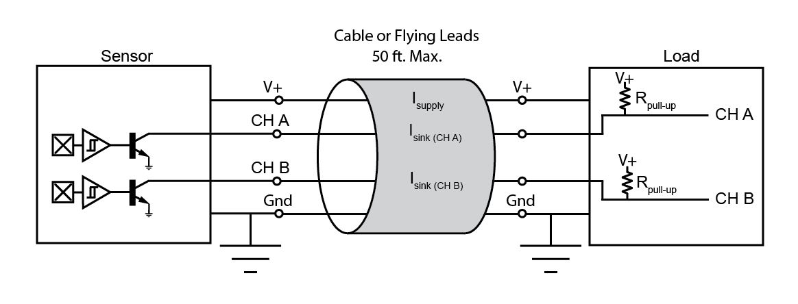
- Output Definition
-
PPR Options 1 to 30
Recommended Pull-Up Resistor Values Current, ISINK 5V Supply 12V Supply 24V Supply 1.2 mA 4.3K 10.0K 20.0K 2.5 mA 2.0K 4.7K 10.0K 5.0 mA 1.0K 2.4K 4.7K 10.0 mA 510Ω 1.2K 2.4K Output channels require customer supplied pull-up resistors unless internal pull-up option is selected.
Output Waveform 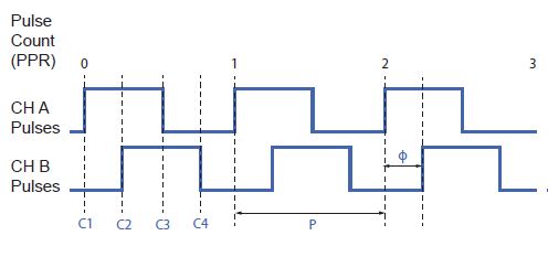
- Target Magnet
-
Molded (A) 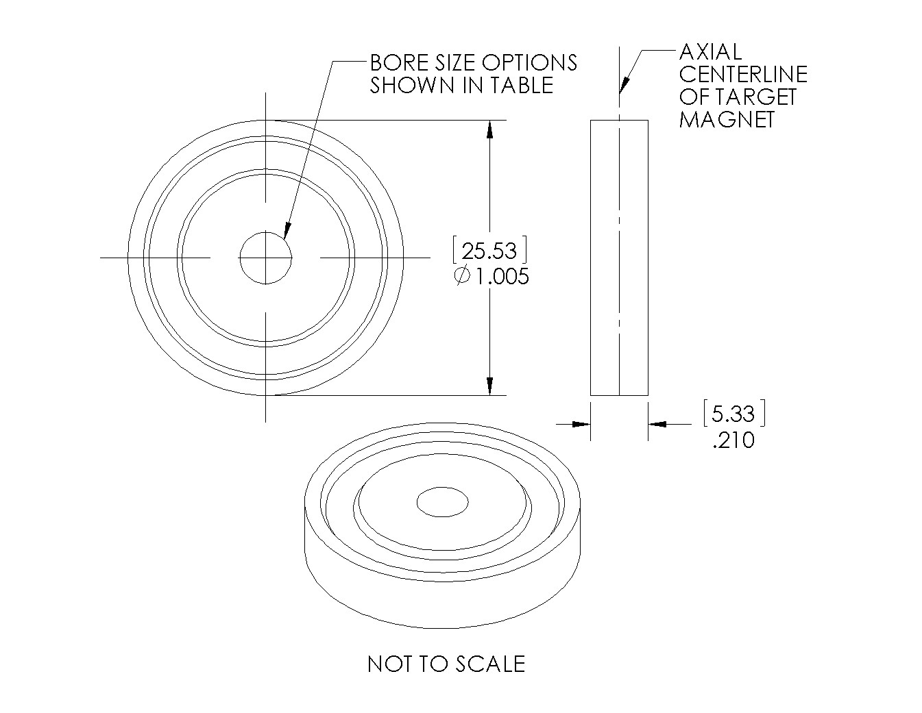
Bore Size
(.inch)
Motor Shaft
O.D. Size
NEMA Guide
Shaft Tolerance
Magnet Bore
MIN.
Magnet Bore
MAX.
079 2 mm +0.0000"/-0.0005"
.0777" .0807" 118 3 mm .1171"
.1201"
125 1/8 in .1240"
.1270"
156 5/32 in .1553"
.1583"
157 4 mm .1565"
.1595"
188 3/16 in .1865"
.1895"
197 5 mm .1959" .1989" 236 6 mm .2354" .2384" 250 1/4 in .2490" .2520" 276 7 mm .2747" .2777" 313 5/16 in .3115" .3145" 315 8 mm .3140" .3170" 375 3/8 in .3740" .3770" 394 10 mm .3930" .3960" 473 12 mm .4718" .4748" 500 1/2 in .4990" .5020" Aluminum Hub (B) 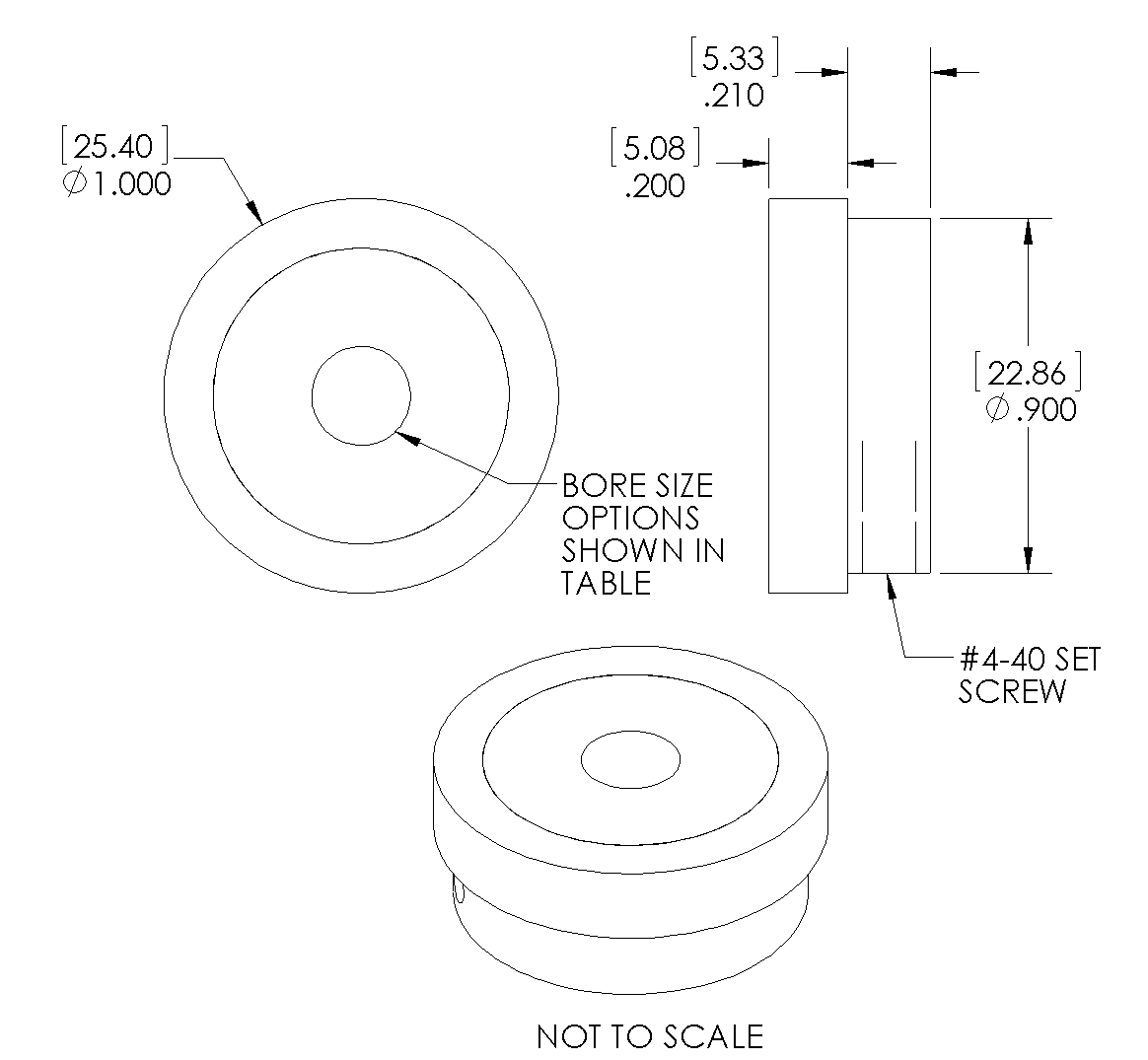
Bore Size
(.inch)
Motor Shaft
O.D. Size
NEMA Guide
Shaft Tolerance
Magnet Bore
MIN.
Magnet Bore
MAX.
079 2 mm +0.0000"/-0.0005"
.0794" .0803" 118 3 mm .1188"
.1197"
125 1/8 in .1257"
.1266"
156 5/32 in .1570"
.1579"
157 4 mm .1582"
.1591"
188 3/16 in .1882"
.1891"
197 5 mm .1976" .1985" 236 6 mm .2371" .2380" 250 1/4 in .2507" .2516" 276 7 mm .2767" .2778" 313 5/16 in .3134" .3145" 315 8 mm .3159" .3170" 375 3/8 in .3759" .3770" 394 10 mm .3949" .3960" 473 12 mm .4737" .4748" 500 1/2 in .5009" .5020" Engineered Polymer Hub (H) 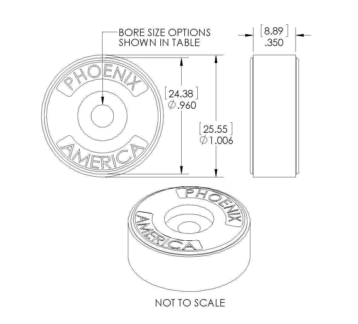
Bore Size
(.inch)
Motor Shaft
O.D. Size
NEMA Guide
Shaft Tolerance
Magnet Bore
MIN.
Magnet Bore
MAX.
079 2 mm +0.0000"/-0.0005"
.0727" .0757" 118 3 mm .1121"
.1151"
125 1/8 in .1190"
.1220"
156 5/32 in .1503"
.1533"
157 4 mm .1515"
.1545"
188 3/16 in .1815"
.1845"
197 5 mm .1909" .1939" 236 6 mm .2304" .2334" 250 1/4 in .2440" .2470" 276 7 mm .2698" .2728" 313 5/16 in .3065" .3095" 315 8 mm .3090" .3120" 375 3/8 in .3690" .3720" 394 10 mm .3880" .3910 473 12 mm .4668" .4698" 500 1/2 in .4940" .4970" - Wiring & Connection
-
Standard Wiring Code Flying Leads Cable Ch A Yellow Brown Ch B Blue Orange Gnd Black Black +VCC Red Red Wiring Options 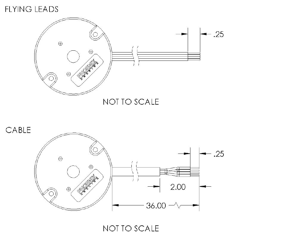
Connector Options 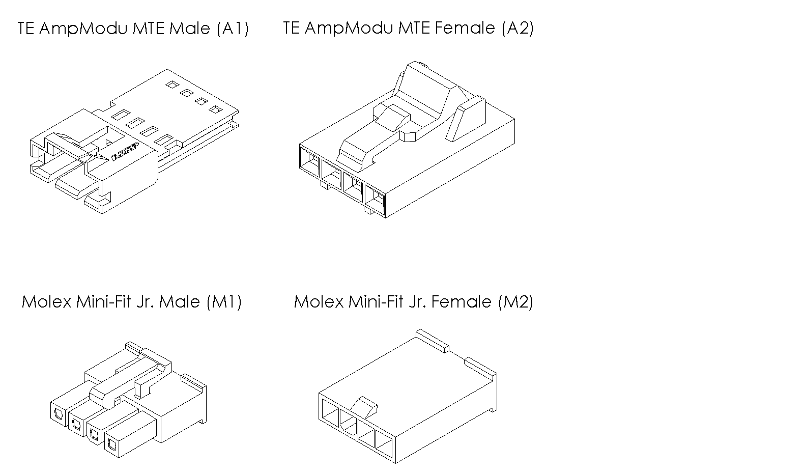
- Assembly Instruction