HJ High Resolution Kit
Quick Overview
- Magnetic technology offers robust performance.
- 100% Non-contacting design (no bearings or bushing) provides an extremely long life expectancy and is tolerant to harsh environments.
- Simple two piece design (target magnet + encoder) for easy alignment and installation.
- Bi-directional two channel incremental quadrature output. Option for differential RS422 compatible output.
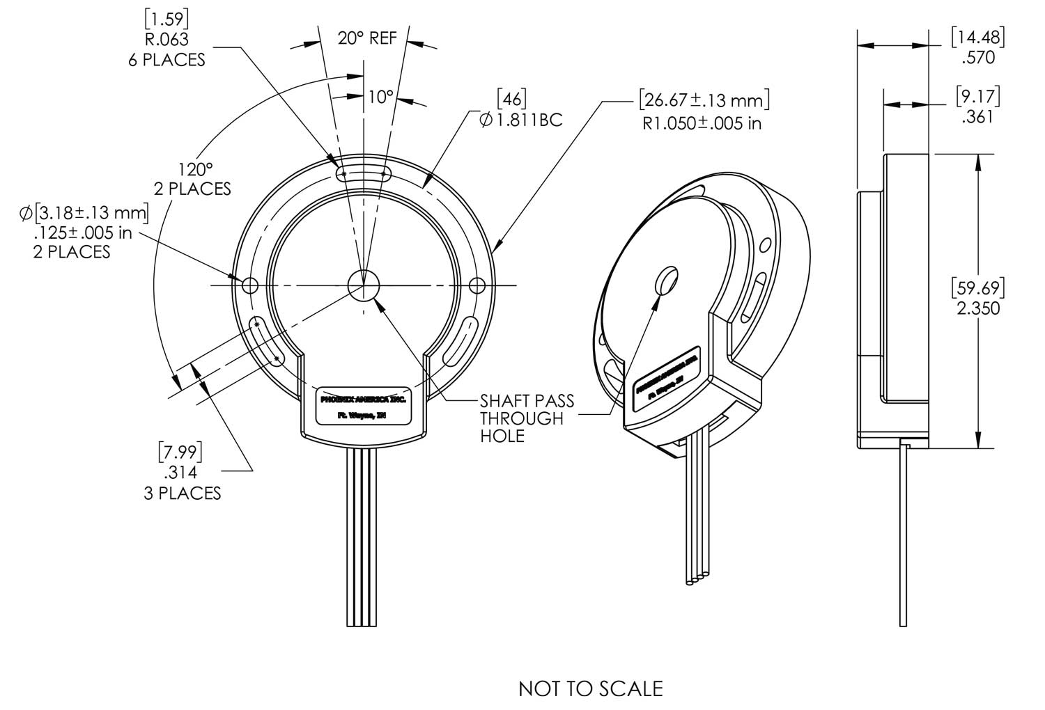
- Mounting holes for a 2-bolt pattern 1.811 inch B.C. x 0.125 inch O.D.
- Target magnet for standard shaft sizes from 5/8 inch to 1 1/8 inch. Custom bore size available.
- Options for 512, 1024, and 2048 pulse per channel per revolution.
- Customizable lead wires, cables, and or connectors.
- Photos
-
-
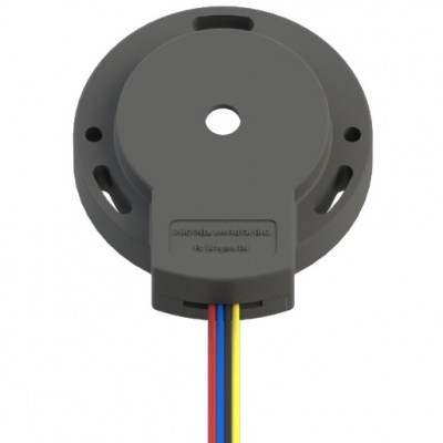 HJ Encoder - Front
 -
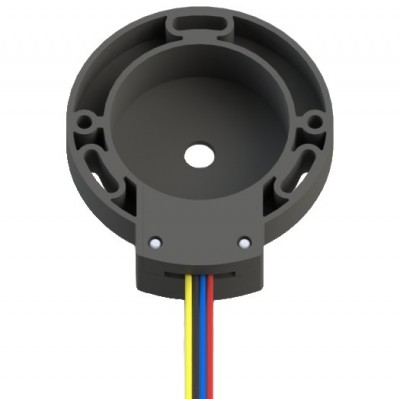 HJ Encoder - Back
 -
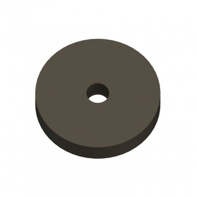 1 3/8 Inch Rotor - Molded
 -
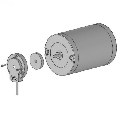 Application Example
-
- Mechanical Drawing Preview


Price:
Product Description
Part Number Configuration Guide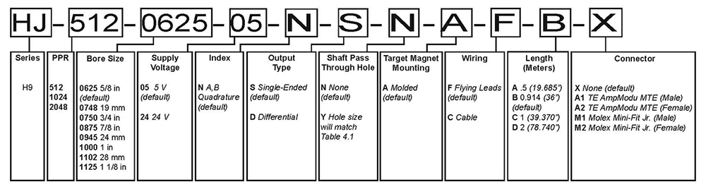
Download
Product Specifications
- Mechanical
-
Characteristic Value Standard Shaft Diameter 5/8 inch - 1 1/8 inch Mounting Screw Size M2.5 Metric / #4 English 2-Bolt Pattern 1.811 inch BC x 0.125 inch OD Motor Shaft Diameter Shaft Pass Through Hole Size 5/8 inch 15.91 mm 0.627 inch 19 mm 19.06 mm 0.751 inch 3/4 inch 19.09 mm 0.752 inch 7/8 inch 22.26 mm 0.877 inch 24 mm 24.06 mm 0.948 inch 1 inch 25.43 mm 1.002 inch 28 mm 28.06 mm 1.106 inch 1 1/8 inch 28.60 mm 1.127 inch - Electrical
-
Absolute Maximums Symbol Rating
for 5V
Rating for
6V to 24V
Units Forward Supply Voltage VCC 6
30
V Reverse Supply Voltage VRCC -0.3 -20 V
Storage Temperature TS 150 150 °C
ESD (HMB, 100pF/1.5Kohm) - 2 2 kV
5V Specifications Symbol Test Condition Min. Typ. Max. Units Supply Voltage VCC Operating,
TJ < 165 °C
4.75 5 5.5 V Supply Current ICC VCC = 12V - 14 20 mA
Operating Temperature TA - -40 - 125 °C Duty Cycle - - 40 50 60 % Phase - - 70 90 110 °e Output Frequency fOUT - - - 42 kHz
24V Specifications Symbol Test Condition Min. Typ. Max. Units Supply Voltage VCC Operating,
TJ < 165 °C
5.25 12 24 V Supply Current ICC VCC = 12V - - - mA
Operating Temperature TA - -40 - 125 °C Duty Cycle - - 40 50 60 % Phase - - 70 90 110 °e Output Frequency fOUT - - - 42 kHz
Electrical Circuit 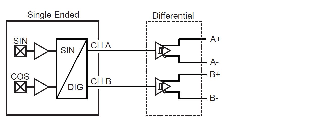
- Output Definition
-
PPR Options 512, 1024, 2048
Single Ended Output Waveform 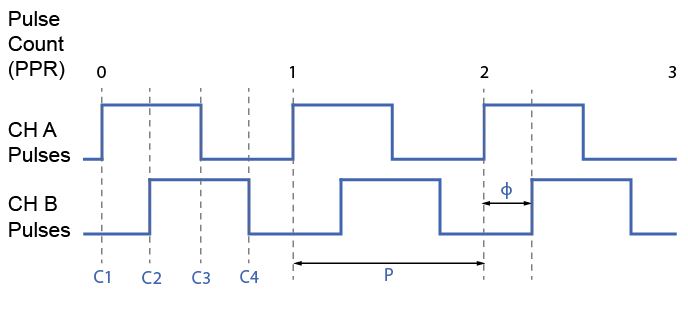
Differential Output Waveform 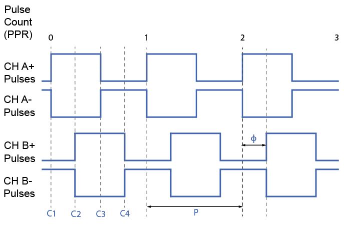
- Target Magnet
-
Molded (A) 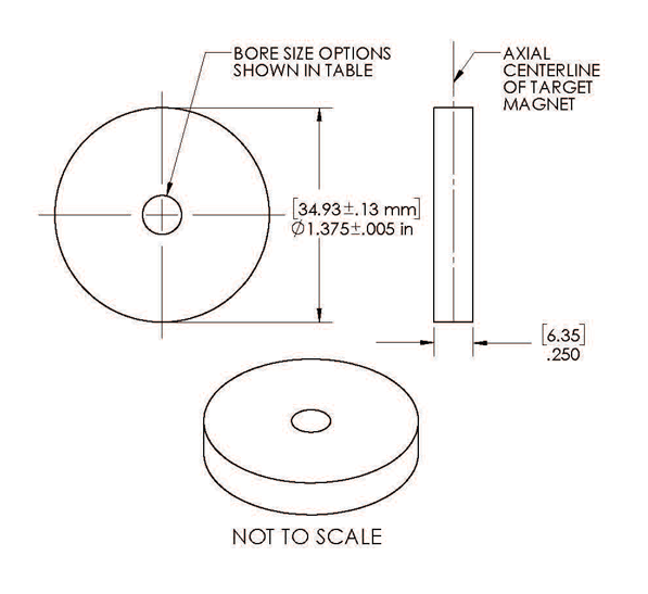
Bore Size
(.inch)
Motor Shaft
O.D. Size
NEMA Guide
Shaft Tolerance
Magnet Bore
MIN.
Magnet Bore
MAX.
0625 5/8 in +0.0000"/-0.0005"
.627" .629" 0748 19 mm .750"
.757"
0750 3/4 in .757"
.759"
0875 7/8 in .877"
.879"
0945 24 mm .947"
.949"
1000 1 in 1.002"
1.004"
1102 28 mm 1.104" 1.106" 1125 1 1/8 in 1.127" 1.129" - Wiring & Connection
-
Single Ended Wiring Code
Flying Leads Cable Ch A Yellow Brown Ch B Blue Orange Gnd Black Black +VCC Red Red Differential Wiring Code Flying Leads Cable Ch B Blue Orange Ch B- Orange Green Ch A Yellow Brown Ch A- Brown Yellow Gnd Black Black +VCC Red Red Wiring Options 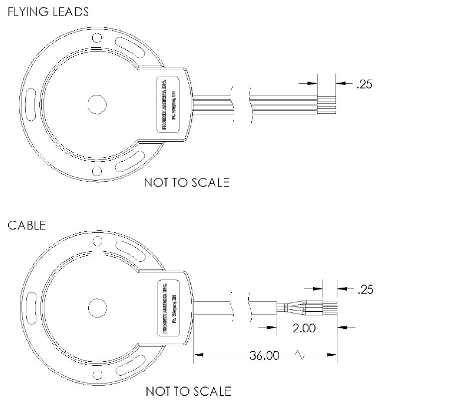
Connector Options 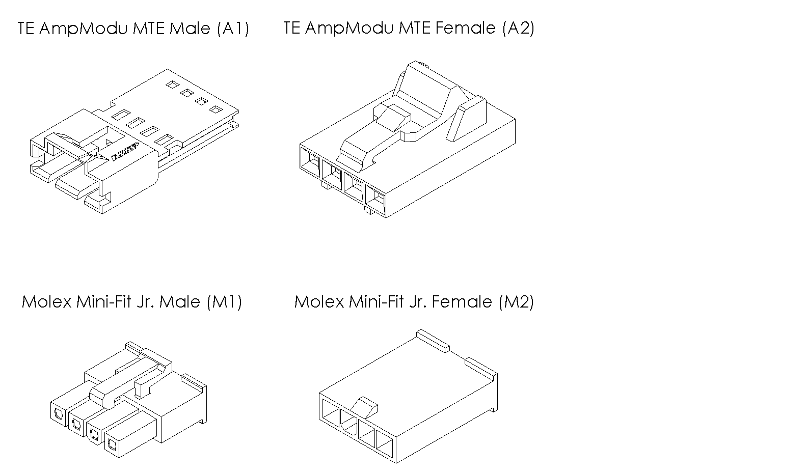
- Assembly Instruction